In this article I want to show you how you can visualize an existing evironment in a network plan.
Network plans help colleagues who are not familiar with a network understanding it faster. They are also very useful to explain certain issues to someone or visualize why a certain investment is important.
Informationen gathering
At first you will have to collect a lot of information about the network you want to visualize. A resource that we often tend to forget about is the already existing documentation that might exist. It might not be complete or out of date but can contain valuable information.
Check the (hardware) firewall -> What networks do exist -> How many Uplinks are there -> Upstreaming Device(es)
Find a way into the network -> VPN -> Remote Access to a server or client -> Scan the network
Check the networking devices -> What devices are there (Vendor, Model, IP) -> Do you have login credentials and do they work? -> How are the devices interconnected (cdp, lldp)
Check the servers -> Physical or virtual? -> In wich Networks are the Servers located? -> What do they do?
Check other devices -> Access Points -> Phone Systems / IP-Phones -> Conferencing Systems -> Printers
Once you got all these Infos available you can begin creating the network plan.
What type of network diagram
It is important that you are aware of what style to choose for what purpose. Is it for example enough to provide an abstract view of the network?
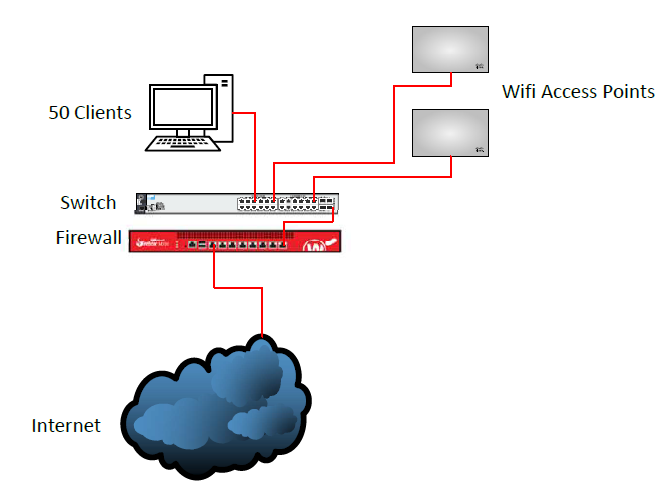
Should the networks be visualized?
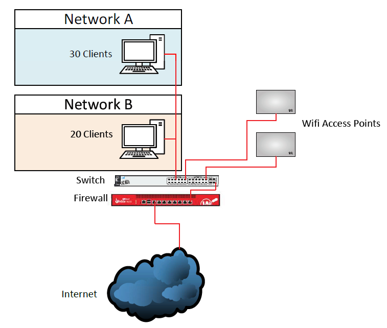
Should buildings be part of the plan?
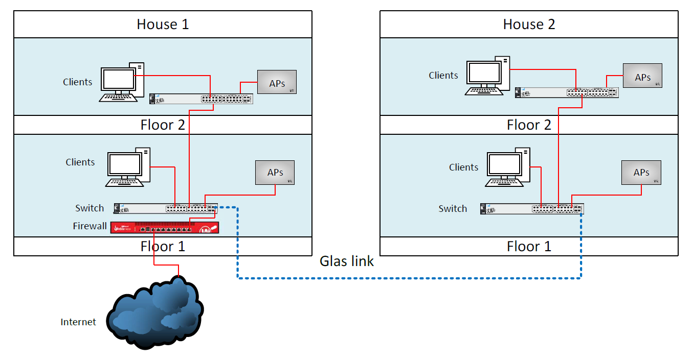
We can scale this up until we visualize infrastructures that span across continents, you get the point.
Do you maybe want a floorplan that is showing the devices? (Good for planing wifi)
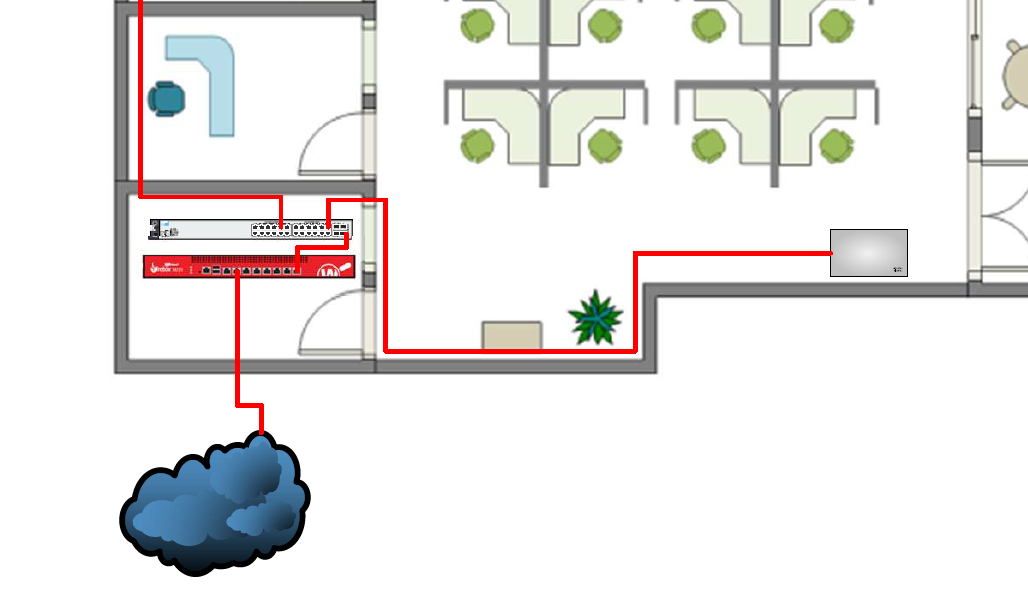
As you can see the type of network plan depends on what it is going to be used for. Do you want to provide an overview over a virtualisation structure with lots of hypervisors, lots of networks and a ton of servers? Then you probably want to have an abstract plan showing the structure of the logical Network.
Is the plan supposed to be used by a technician to be able to find physical devices at a location? Then you probably want a plan that is as close to the physical reality as possible.
These concepts nearly always get mixed to some point. However when you have really complex plans, it might be better to have two or more separate plans suited for the right purpose. When you are trying to force every available information into one network plan you can end up making it unreadable and therefor unuseful.
As you can see, creating a network diagram is a form of art in itself.
Creating the network diagram
I am currently using the non-free software Visio from Microsoft to create network diagrams.

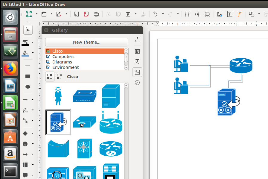
You could also just use GIMP if you want to create a network diagram, its up to you. At this point I assume you already made up your mind what type of diagram you want to create and what software you are going to use.
If you are going to use floorplans or want to visualize buldings / floors, start by doing that. Once that is complete feed all the information you gathered in the information gathering process into the network plan. Start at the Internet Uplink and then go down the Line.
Uplink > Router > Firewall > Switch(es) > Devices attached to the Switches (Servers, Clients etc.)
It is a good idea to write important IP addresses and hostnames into the network diagrams. Also it is a good idea to not only write down physical servers but also virtualized ones.
End-User devices can usually be culminated into a group. (20 Workstations, 15 mobile devices, etc.)
Cheers, Ori